4. Overcharge
Test Conditions
Charge the lithium-ion battery to a state that is far above its charge cut-off voltage (above 4.6V) or far above its rated capacity (above 110%)
Failure principle
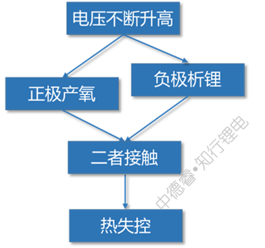
When overcharged to a higher voltage, the positive electrode will decompose to produce oxygen, and at the same time the negative electrode will severely precipitate lithium. When the two meet, it is natural to spark out.
Monitoring the changes in cell voltage and temperature during the overcharge process can overcharge into four stages, as shown below:
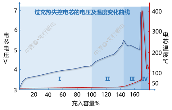
The reactions that occurred in the intervals shown in the figure above are as follows:
(I) is the normal charging process of the battery cell;
(II) The battery has entered an overcharge state, but at this time, only lithium deposition at the negative electrode has occurred, and the positive electrode has not been decomposed in large quantities, so it has not caused an abnormal increase in the temperature of the battery cell;
(Ⅲ) When the positive electrode begins to decompose to produce oxygen and release a lot of heat, the temperature of the cell increases, the internal resistance of the cell decreases due to the increase in temperature, so the polarization is weakened and the voltage of the cell decreases slightly;
(Ⅳ) The thermal runaway of the battery cell caused the voltage and temperature to rise suddenly and suddenly.
The causal chain diagram describes the failure principle of overcharging as follows:
Improvement plan
Improvements for "increasing voltage"
Lithium-ion batteries continue to be overcharged, and you must expect the voltage to not increase. You can consider two directions: cut off the charging circuit or release the charged power through other means.
(1) Cut off the charging circuit: If you want to study the problem of cutting off the charging circuit, you must first figure out what the circuit is during the charging process: external circuit → positive ear → aluminum foil → positive electrode → electrolyte → separator → electrolyte → negative electrode → copper foil → Negative ear → external circuit.
In addition to knowing where the cut-off may be, we also need to know the incentives for the cut-off. For overcharging, the main causes are the increase in voltage and the increase in temperature. Knowing the location and incentives of the cut, we can find many possible improvements:
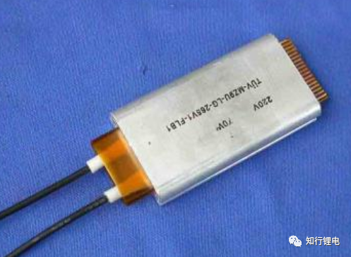
Using temperature as an inducement, cut off the external circuit and the positive ear, for example, add PTC protection on the cell:
Using temperature as an incentive, cut off the aluminum foil and the positive electrode dressing, for example, apply a layer of PTC coating on the surface of the aluminum foil:

Using temperature as an incentive, cut off the positive and negative electrode dressings and electrolyte, for example, coat a layer of PTC coating on the surface of the active material:
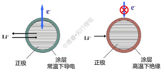
For the above-mentioned PTC coating materials, the resistance at high temperature will increase significantly:
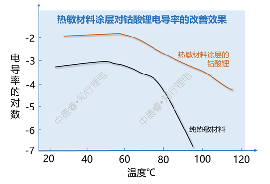
(2) Release charging energy: There are two schemes for flood control: blocking and sparseness. Naturally, there are two methods for dealing with overcharged current: cutting the loop and releasing energy. When releasing energy, the following methods can be considered:
Making a voltage-sensitive diaphragm: filling the diaphragm with an electroactive polymer to insulate the electronics within the normal voltage range, but when the voltage rises to the overcharge range, the filled polymer is oxidized to a conductive substance, which is equivalent to letting the positive and negative electrodes The active material is short-circuited, and at the same time, the positive electrode is further increased in voltage to generate oxygen and the negative electrode to release lithium.

Electropolymerization short-circuit method: a polymer monomer molecule is added to the electrolyte. When the positive electrode potential is increased to a certain degree, the monomer molecule will be converted into free radicals and polymerized with the electrolyte and deposited on the positive electrode, the deposit will gradually Growth and eventually cause a short circuit in the positive and negative electrodes.
Add redox couple to the electrolyte. When overcharged, the additive will be oxidized at the positive electrode, and then diffused to the negative electrode to be reduced. This cycle repeats and continuously consumes the energy of the overcharge.

Combining the above improvement methods, the problem of "cutting" is mainly the compatibility of PTC and the core material, and the problem of "sparseness" is not only the compatibility of the material, but also the need to consider that the released electrical energy will be converted into the thermal energy of the core to cause electricity. The core further generates heat.
Improvement for "positive oxygen production"
After the positive electrode is overcharged, it does not produce or produces less oxygen. One direction is to start directly from the perspective of materials. Choosing to still exist lithium iron phosphate or lithium manganate under high voltage is still possible.
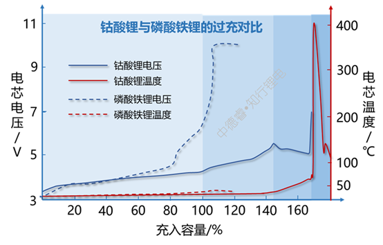
Lithium iron phosphate overcharge hardly produces oxygen, so there is no stage Ⅲ, Ⅳ
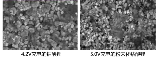
The other direction is to coat or blend the positive electrode. For example, coating AlPO4 on the surface of lithium cobalt oxide or physically blending other positive electrode with higher safety will also improve the stability of the positive electrode to a certain extent. For ternary materials, they are generally made into single crystal particles to improve the stability of the high voltage state.
Improvement for "Negative Lithium Evolution"
The most direct way to prevent excessive lithium ions from the positive electrode from coming to the negative electrode is to increase the negative electrode excess. Secondly, it is also necessary to pay attention to the ionic conductivity of the negative electrode and the electrolyte, to prevent the lithium from being released due to the inability of lithium ions to be intercalated in time when the battery is overcharged.
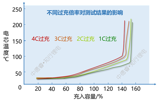
It can be seen from the above figure that increasing the overcharge rate will slightly reduce the capacity charged during thermal runaway. The main reason is that the lithium precipitation is more serious under high rate charging conditions, and more Joule heat is also generated.
Improvement for "Oxygen and Lithium Contact"
I have been confused when I did the charging test before: obviously the temperature of the cell is less than 100 degrees, why did it suddenly catch fire? It was later learned that the decisive factor for overcharging is not the temperature, but the severity of oxygen production and lithium evolution. When the amount of the two reaches a certain concentration inside the cell, even if it is only room temperature, it is very dangerous.
A possible way to avoid contact between oxygen and lithium is to increase the exhaust valve at the location of the cell packaging, or to reduce the seal strength of the soft battery in some locations, and to expel oxygen when the internal air pressure increases.
doubt:
Does the decomposition of the electrolyte during overcharge have a great effect on the thermal runaway of the battery?
Severe conditions of overcharging can make the cell voltage easily exceed 5V, which has greatly exceeded the stable voltage of the electrolyte (for details, please refer to a picture to understand the full voltage characteristics of lithium ion batteries), the electrolyte will be generated under high pressure CO, CO2, CH4, C2H4 and other gases, and the chain esters DMC and DEC will also gasify at high temperature.
However, according to an experiment conducted by Wenwu (in the case of 80% excess negative electrode, the high-energy density design lithium cobalt oxide battery is overcharged and not fired or exploded), it is known that even if the electrolyte is decomposed at high voltage, these products encounter oxygen generated by the decomposition of lithium cobalt oxide, which is not enough It will inevitably cause a fire, because the temperature of the cell after overcharging is only about 100 ℃, which is not the same as the high temperature generated by thermal shock and needle punching. Therefore, after the electrolyte is overcharged, the product is more "pouring oil on the fire" after the battery has been thermally out of control, but it cannot play the role of "sending carbon in the snow".

Will the pure anode emit lithium and the cathode does not produce oxygen, will it cause overcharge and runaway?
In this article, Wen Wu attributed the cause of runaway overcharge to the common result of "positive oxygen production + negative electrode lithium evolution". In the previous paragraph, it was introduced that pure positive electrode oxygen production will not cause thermal runaway. Is it causing thermal runaway?
The experimental scheme closer to this state is 111 ternary + graphite, and the stability of 111 ternary material at high voltage is significantly stronger than that of lithium cobalt oxide, so it may not produce oxygen when overcharged but at the same time cause lithium precipitation in the negative electrode Case. According to experience, we know that ternary batteries have a low probability of passing the overcharge test. Some safety-designed batteries also use ternary + anti-overcharge electrolyte to pass the strict overcharge test, indicating that the risk of pure lithium analysis is higher than Lithium analysis + oxygen production is much smaller, so this article does not list this item separately.
It needs to be added that when the separator has a higher puncture strength, it can delay the lithium puncture of the separator and the short circuit in the cell caused by the lithium deposition, so it also has a certain improvement effect on overcharge (provided that the positive electrode Basically does not produce oxygen).
Overcharge summary
Failure principle: sparks from overcharge of positive electrode and lithium precipitation from negative electrode
Key improvement points: the stability of the high voltage of the positive electrode and the excess of the negative electrode
Possible improvement points: cut off the charging circuit, release the charging energy, the diaphragm with higher puncture strength
Brainstorm improvement point: release the generated oxygen
5. Overdischarge
Test Conditions
Discharge the lithium ion battery to 0V or negative voltage
Failure principle
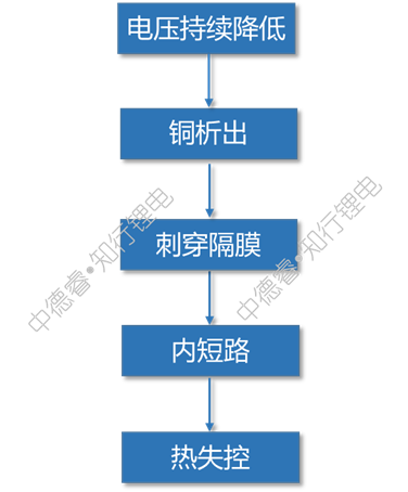
After the battery is severely over-discharged, the negative electrode copper foil will precipitate on the surface of the positive electrode after dissolving, there is a risk of puncturing the separator and causing an internal short circuit.
However, due to the few heat generation during copper precipitation, the precipitated copper is less prone to produce dangerous dendrites, and the poor activity of copper compared to lithium, the risk of overdischarge is much smaller than that of overcharge, which is a relatively mild Safety test.
The causal chain diagram describes the failure principle of overdischarge as follows:
Improvement plan
Improvement for "voltage drop to 0V"
The general idea is the same as the improvement of overcharging. Two methods of "blocking" (using a thermal element to cut off the circuit) and "sparse" (causing an internal short circuit in advance) can be considered. However, due to the small temperature change during over-discharging, the use of thermally sensitive originals is limited; at the same time, the serious result of over-discharging is internal short circuit, and the value of "sparse" is not great.
Improvement for "copper precipitation"
Taking the ternary + graphite system as an example, during a complete charge + discharge + over discharge process of a lithium-ion battery, the changes in the positive and negative electrode voltages are shown in the following figure:

The explanation of the above charging and discharging process is as follows:
(I) is the formation stage, where V0 is the initial voltage difference when the positive and negative electrodes are not charged and discharged, and is the voltage after the cell is filled with liquid;
(Ⅱ) (Ⅲ) is the normal charge and discharge stage;
(Ⅳ) This is the first stage of over-discharging. The characteristic of this stage is that the lithium ion of the graphite anode has been deintercalated in III. At this time, the decomposition of the negative electrode SEI film mainly occurs. At this time, the negative electrode voltage increases rapidly and the voltage of the entire battery Then decrease rapidly;
(V) is the second stage of over-discharge. At this time, the negative electrode potential is stable at 3.56V (vsLi+/Li). This potential is the dissolution potential of copper. Dissolved copper ions are not immediately deposited in the positive electrode, but remain in the negative electrode or dissolve in the electrolyte, and then gradually precipitate out of the positive electrode. At this time, the main lithium intercalated into the positive electrode is the excess lithium ions from the electrolyte. The voltage of the positive electrode continues to decrease.
(VI) is the third stage of over-discharge. At this time, the positive voltage has a rebound after experiencing a minimum value. The voltage after rebound corresponds to the copper precipitation potential. At this stage, almost no lithium ions are inserted into the positive electrode. The reaction of the positive electrode is mainly the precipitation of metallic copper, and at the same time, the risk of internal short circuit caused by the penetration of the metallic copper by the separator is gradually increased.
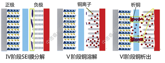
From the above analysis, it can be seen that the main method of dissolving copper when delaying over discharge is that the delayed negative electrode voltage rises to 3.56V during the discharge process. There are three main methods:
(1) Use a positive electrode with a lower voltage platform such as lithium iron phosphate: the copper precipitation potential of the negative electrode is fixed, and we can only control the full battery voltage during use. Therefore, when the positive voltage platform is lower, the full battery analysis The lower the voltage required for copper, the iron-lithium full battery even needs a negative voltage to analyze copper, and the ternary or lithium cobalt oxide full battery shown in the above figure may cause copper precipitation at a positive voltage.
(2) Increase the first negative electrode efficiency: When the first negative electrode efficiency is relatively high, after the positive electrode is filled with lithium ions, the negative electrode still has surplus carbon-lithium compounds, so it will not immediately enter the over-discharge stage Ⅳ and Ⅴ, which reduces the analysis. Copper risk.
(3) Raise the discharge cut-off voltage of the whole battery: At present, the discharge cut-off voltage of about 3V, and the positive voltage of 6V or more is required for copper precipitation, which is obviously very safe.
(Because the risk of overdischarge is not high, it is generally not necessary to carry out special design to improve overdischarge, and the corresponding improvements in the last three steps in the causal chain diagram are omitted.)
Doubts: Why do you find copper deposits after disassembling the battery after cycling?
During the cycle, the SEI film will be continuously consumed and reformed, which gradually consumes the lithium source, and eventually causes the anode to be poor in lithium and the anode voltage is getting higher and higher. During battery use, the voltage may spontaneously fall below the copper precipitation voltage during battery storage. Too much SOC difference in the same series of batteries will also cause low SOC battery over-discharge. The combination of the above reasons increases the probability of occurrence of copper precipitation.
Overdischarge summary
Failure principle: over-discharge causes the precipitation of negative electrode copper, puncturing the diaphragm and causing internal short circuit
Key improvements:/
Possible improvements: low voltage platform positive electrode, high puncture strength diaphragm
Brainstorm improvement points: use voltage sensitive materials to cut off the over-discharge circuit
6. External short circuit
Test Conditions
Connect the positive and negative pole lugs directly with conductors
Failure principle
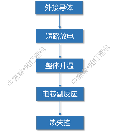
Because the resistance of the external conductor is very low, the cell will discharge at a very large rate. The internal temperature continues to increase with the discharge process. At the same time, it may be accompanied by the melting of the diaphragm and the excessive release of copper, which eventually leads to thermal runaway.
The causal chain diagram describes the failure principle of external short circuit as follows:
Improvement plan
Improvement for "short circuit discharge"
As mentioned in the improvement of overcharging, the most commonly used method here is to cut off the short circuit. Specifically, the means include an external PTC electrode, a foil coated with a thermosensitive material, or a positive and negative electrode active material coated with a thermosensitive material, etc. Several kinds. Because the short-circuit current is much larger than the overcharge current, the high temperature generated by the short circuit is also significantly higher than that of the overcharge. Therefore, the improved method of "cutting the circuit with heat-sensitive materials" is more effective for short circuits.
If the short circuit cannot be cut off, it is also a good solution to appropriately reduce the short circuit current. The decisive influencing factor of short-circuit current is the level of external resistance, the higher the overall short-circuit current is, the slower the temperature rise during short-circuit:
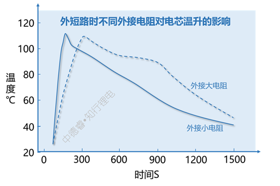
Although the external resistor has a high resistance value, it slows down the heating rate, but the maximum temperature of the cell does not decrease significantly. The main reason is that the electric energy of the cell is basically converted into the thermal energy of the cell during a short circuit and causes a temperature rise. During this period, the heat dissipation difference and external Resistance sharing heat is limited, so the maximum temperature difference is not large.
In the same way, if the internal resistance of the cell itself is relatively large (for example, the winding is relative to the lamination), the heating rate can also be slowed down, which theoretically improves the safety of the short circuit. However, when choosing between "better rate performance" and "slower short-circuit temperature rise", most people will choose the former.
Improvement for "overall temperature rise"
The risk of thermal runaway caused by an external short circuit is not too high. One reason is that almost uniform heat generation occurs inside the cell, rather than local heat generation like acupuncture, and the maximum temperature is only more than 100 ℃, so it is simple The temperature rise caused by an external short circuit is generally not sufficient to directly cause thermal runaway.
However, because temperature rise may further cause other side reactions, deliberately consider adding some excellent thermal conductor materials inside the cell, such as graphene, metal sheet, heat dissipation silicone, etc., to speed up the overall heat dissipation of the cell.
Improvement for "Battery Side Reaction"
When the battery cell is externally short-circuited, the side reactions that may be caused by high temperature are as follows:
Diaphragm shrinkage: The high temperature caused by the external short circuit is generally around 130℃, which is enough to cause the melting of the PE diaphragm, but has little effect on the PP diaphragm.

Similar to the thermal shock mentioned above, the result of external short circuit melting of the diaphragm is mainly due to the direct contact of the positive and negative electrode dressings, the heat generation is not too high, and the possibility of failure is not high.
The melting of the pole ear: When the material of the pole ear is aluminum or nickel with insufficient conductivity, and the cross-sectional area is not large enough, the external short circuit may cause the pole ear to generate excessive heat and fuse. Although the effect is similar to the PTC cut-off circuit, it still needs to be improved due to the possibility of open flames. The main method is to use copper substrate + aluminum plating & nickel pole.
Cathode copper deposition: After the cell is short-circuited for a long time, the voltage will drop to 0V, which will cause the risk of copper deposition. However, since the amount of copper deposition on the external short circuit is not large and the risk of copper deposition is not high, there is no need for deliberate improvement.
External short circuit summary
Failure principle: external short circuit causes overall temperature rise, internal melting of the diaphragm or melting of the lug further increases the risk
Key improvements: diaphragm material, pole ear material
Possible improvement points: PTC external PTC
Brainstorming improvement points: improve the heat dissipation efficiency of the cell, the heat-sensitive material coated foil or the main material
Safety summary
Who is the hardest to pass the safety test?
Acupuncture: Lithium iron phosphate anode and vest can greatly improve the passing probability. The thin and large cell size also helps to increase the passing probability, but under other conditions, the difficulty of passing is quite high;
Overcharge: The lithium iron phosphate positive electrode and the increase of the negative electrode can greatly increase the probability of passing. The two methods of external PTC, anti-overcharge electrolyte and ternary materials also have a certain degree of improvement, and other solutions are limited;
Heavy object impact: It can be used as a small needling, the improvement scheme is similar to acupuncture, but the probability of failure is lower, and the width and rigidity of the cell may have a significant impact;
Thermal shock: changing the material of the diaphragm can greatly improve the probability of passing, and even if the PE substrate diaphragm is used, it will only cause a short circuit between the positive and negative electrodes and the copper and aluminum foil with a low risk, and the probability of failure is low;
External short circuit: It can be regarded as a large thermal shock. The temperature of the cell is basically the same as the thermal shock, but the heat generated by the pole ear and the rapid internal reaction increase the risk of failure;
Over-discharge: This is written mainly to talk about copper analysis.
In summary, the difficulty ranking of each safety test is: acupuncture ≈overcharge>heavy object impact>external short circuit>thermal impact>overdischarge
Who are the design elements that have the greatest impact on safety performance?
According to the above difficulty ranking, we ranked the difficulty of the six safety tests from 5 to 1, with 5 points for acupuncture and overcharge, 4 points for heavy impact, 3 points for external short circuit, and 2 points for thermal shock. Discharge 1 point.
According to the safety improvement plan listed by Wenwu, we divide all the design elements into ten categories: positive electrode, negative electrode, separator, electrolyte, aluminum foil, tab, cell structure, cell shape, heat-sensitive material, and special case. The relationship between design elements and safety testing is listed as ◎ for key impacts, ○ for general impacts, and △ for possible impacts. The following table is listed:
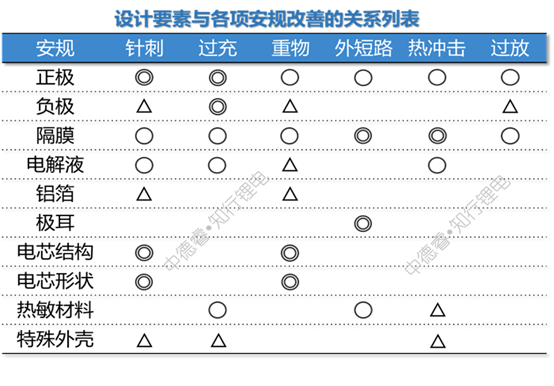
Next, we borrowed the principle of priority matrix chart, rated the critical impact as 5 points, the general impact as 3 points, and the possible impact as 1 point, and multiplied the degree of impact of each item with the difficulty of the corresponding safety test to calculate Give the total score of each design element:
For example, the total effect of the positive design element on safety regulations = 5 (critical to acupuncture) ╳5 (difficulty of acupuncture) + 5 (critical to overcharge) ╳5 (difficult to overcharge) +3 ╳4 +3╳3+3╳2+3╳1=80 points.
We use the above algorithm to calculate the safety impact of all design elements, and make the final result into a histogram:
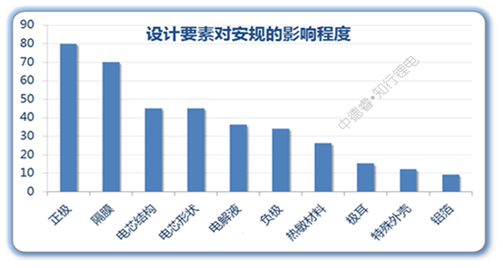
Since the positive electrode and the diaphragm have a general or critical impact on all safety tests, the two have the highest scores; the cell structure and the shape of the cell can significantly improve the two harsh external force safety regulations, such as needle punching and heavy object impact. , The score is also high; under the existing system, the negative electrode and the electrolyte can be optimized with little space, and generally it is not a short board that fails, so the score is not high. If the flame retardant electrolyte used for mass production is subsequently developed, The situation will change.


